This Month’s Articles:
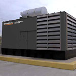
- Generac Expands & Enhances Industrial Portfolio
- Understanding NEC Code for Standby Generators
- Is it Time for a Coolant Flush?
- Study for Department of Defense Suggests that the US Natural Gas Infrastructure Could be Considered Onsite Storage
- Make Plans to Attend Generac’s Annual Engineering Symposium
Generac Expands & Enhances Industrial Product Portfolio
 Generac Industrial Power has revamped its large kW product line with three new power generators, and a new integrated paralleling control. Additionally, two existing models received system upgrades, improving performance, functionality, and competitiveness.
Generac added the 750 kW, 900 kW, and 1500 kW diesel generators to its industrial product line, creating a complete offering from 750 kW to 2 MW. They can be used as either a standalone SD series generator or as an MD series generator in Generac’s innovative, marketing-leading paralleling Modular Power System (MPS) with outputs up to 100 MW of power. All of the generator systems are available in an open set configuration, or with weather protected, Level 1, or Level 2 sound attenuated enclosures.
All industrial generators up to 2 MW are manufactured in Generac’s Wisconsin facilities, offering engineers and contractors a fully integrated solution from a single source of accountability.
“Generac continuously invests significant resources into research, innovation and product development, which is why we can offer this breadth of line that meets even the most strict customer requirements,” said Russ Minick, Generac Power Systems’ Executive Vice President of North American Sales. “Generac has effectively doubled its industrial product range, and we’re excited at how fast we have expanded our industrial product offering, thereby becoming a true full-line solution provider. If you need a large, industrial generator, go big with Generac.”
The generators are designed to give engineers and contractors the option to choose from a wide range of Generac alternators with optional temperature rises for improved motor starting in stringent application needs. Both 40°C and 50°C ambient cooling systems are offered with an enhanced option to meet various ambient temperature application requirements, while optional critical- and-hospital-grade exhaust silencers enhance sound attenuation. The robust Mitsubishi Heavy Industries engines offer market-leading altitude derates as well.
Other features include:
- Full range of multiple unit-mounted circuit breakers up to 3000A
- Listed to UL2200 from factory
- NFPA 110 compliant
- UL142 listed fuel tanks for 12 and 24 hour runtimes to meet various code requirements
For information on the units engine displacement and power ratings, click here.
Generac’s new, highly-reliable PowerManager System Control (PM-SCi) is ideal for project managers looking for a more cost-efficient and space saving MPS solution for paralleling multiple large generators. The advanced integrated (on-board) paralleling and load management capabilities allows for the management of up to 31 paralleled generators, and can control multiple, separate transfer switches. There are six default levels for priority loads and three default levels for load shedding during system failure. The control’s flexibility enables users to add both priority load and load shed levels in boolean logic. The built-in Modbus® technology allows for remote monitoring.
Other key features include:
- Touch-screen display
- Diagnostics capabilities through InteliMonitor® software
- Data logging and trending capabilities
- Programmable exerciser
- Backup mode
Generac’s industrial generators and the PowerManager System Control (PM-SCi) are now available for purchase.
Click here for more information.
Understanding NEC Code for Standby Generators: Cabling, Sizing, Startup and Disconnect

Is the cabling from the generator a feeder or a service?
This is a basic question that has a significant impact with respect to interpreting generator installation requirements. NEC 100 defines a service as being supplied by an operating utility. Therefore, the conductors from the generator are classified as a feeder.
How should the cabling be sized?
Most generators have a single, fully rated output breaker or multiple smaller ones. When the generator has a single output, the breaker is normally sized 100% to 125% of the rated output amps. The cabling is selected to match the generator’s output breaker(s). Many contractors and engineers will typically size to meet the full breaker output capacity. Others will size using the NEC 240.4(B) roundup rule which allows the generator cabling to roundup to the next nominal breaker size (aka a 500 mcm cable rated at 380 amps could be used on a generator’s 400 amp breaker).
The other option for cable sizing is to follow the guidelines in NEC 445.13 which sizes the cabling at 115% of the generator’s rated amps. This method is typically utilized when the generator does not include on output breaker. NEC 445.13 also allows the cabling to be sized for 100% of the generator’s rated amps provided the generator is designed to prevent overloading. With today’s generator digital controls, it is fairly easy to apply overcurrent protective trip functions. We would recommend coordinating with your local authority having jurisdiction (AHJ) prior to sizing with this method to assure consensus.
The final cable sizing method is chosen when utilizing main bus bar (no breaker configurations) to better facilitate selective coordination. In these applications, it is possible to cable multiple disconnects to the generator bus following the NEC feeder tap guidelines.
What does the NEC require for generator sizing?
The answer to this question varies based on the type of load being powered. Emergency systems require the generator to be sized for the entire connected load (NEC 700.4). But if the emergency system is a healthcare application, NEC 517.30(D) requires the generator to meet the peak demand of the load and waives the requirements of NEC 700.4. This was a direct result of healthcare applications being too lightly loaded.
Legally required standby and optional standby have traditionally required the generator to be sized to meet the peak demand of the load intended to be operated. This requirement has been strengthened in the 2008 code for optional standby applications. These applications now require compliance with Article 220, “Branch-Circuit, Feeder, and Service Calculations”, or another AHJ method. This change was driven by a desire to protect the consumer in the residential market from installing a generator smaller than the potential load. For commercial/industrial optional standby applications, we typically find that a Professional Engineer (P.E.) stamped drawing is considered acceptable sizing practice by most AHJs.
How quickly must a generator startup and transfer?
The common answer to this question is 10 seconds. Emergency systems (NEC 700.12) and fire pumps (NFPA 20 9.6.2.1) require a 10 second start and load transfer. Legally required loads require a less demanding 60 second response (NEC 701.12) and optional standby does not require an automatic startup and transfer time. Meeting a 10 second startup time is generally not an issue for single generator applications; however, applications with multiple generators often take a few extra seconds to parallel generators. To meet the 10 second requirement, these applications need to transfer the emergency system loads onto the first generator and then add lower priority loads later.
Is a disconnect required on the generator?
NEC 445.18 shows a preference for the generator to be equipped with a disconnecting means but does allow that disconnect (typically the generator breaker) to be removed provided the generator can be readily shutdown, can be locked out from restarting, and does not operate in parallel with other sources. Though the NEC does allow the generator to be provided without an output breaker, standard industry practice is to typically include this disconnect.
In addition to the generator breaker, is another disconnect required at the point of building entrance?
This is an interesting question because the market implementation of this requirement seems to be split – half the market requires an additional disconnect and half does not. Since the cabling from the generator is a feeder, NEC 225.31 requires disconnect at the point of building entry unless exempted in another part of the code. Enter the local interpretation of the requirements for an outdoor housed generator set (NEC 700.12(B)(6), 701.11(B)(5), 702.11) which states: “Where an outdoor housed generator set is equipped with a readily accessible disconnecting means in accordance with 445.18, and the disconnecting means is located within sight of the building or structure supplied, an additional disconnecting means shall not be required”. The interpretation issue is based on what needs to be visible from the building. Many markets accept generator visibility as acceptable. In these markets an additional disconnect is not required provided the generator is within 50 feet of the building. If the market norm is to only accept disconnect (versus generator) visibility, an additional disconnect would normally be required as most generator breakers are not visible from the building.
Another way to consider the local variation on this issue is based on intent. The intent of 225.31 was to ensure power being fed from one building into another could be quickly and easily disconnected in emergency situations. Since the generator is normally placed near the point of building entry, many markets may be comfortable with disconnect capability built into the generator. Again, check with AHJ to be certain.
If you have questions about the NEC code, please contact us.
Is it Time for Coolant Flush?

- Overheating while running
- Buildup of rust/debris in the coolant system
- Excessive wear on the engine
- Corrosion of coolant system parts
- Premature engine failure
- Costly repair bills
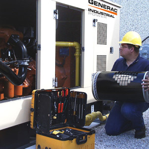
Our technicians can perform the generator coolant flush as part of your generator’s annual maintenance. The technician will check your cooling system to identify any leaks. Rust, corrosion and contaminated engine coolant will be removed. The cooling system will be refilled with the appropriate ratio of water and anti-freeze. Hoses will be checked for stability. If any deterioration is noted, a recommendation for replacement will be made.
Schedule your generator coolant flush and fill today to protect your investment and ensure your generator will be at peak performance in the event of a power emergency.
Study for Department of Defense Suggests that the US Natural Gas Infrastructure Could be Considered Onsite Storage

“Initially, the study appears to fly in the face of logic as electricity is needed for natural gas production,” said John Hoeft, Generac Power Systems’ Director of Power Solutions Management. “However, once the natural gas has been extracted from the ground, the system is much less dependent on the electrical grid. Furthermore, the large number of wells combined with historically reliable transmission and distribution systems, makes natural gas a resilient fuel option for backup power.”
Overview of the U.S. Natural Gas Delivery System
There are three main components in the natural gas delivery system:
- Gathering of gas from multiple small wells
- Transmission of gas by long-distance pipelines
- Distribution of gas to local customers
Natural gas is collected from multiple small wells that are powered by two main methods – gas that comes from the well (self power) and electric motors dependent on a local supply. Electric motors tend to be more common in locations that have stringent emissions requirements, such as California and Colorado (Diesel motors are also used, but that is primarily for off-shore production.)
Once the gas is extracted, it is compressed and sent to the processing plant. At the processing plant, water, natural gas liquids, CO2 and other impurities are removed. There are many gas processing plants located throughout the country to serve various regions so no one area of the country is vulnerable (see map).
Source: US Energy Information Administration
Once clean, dry gas is produced, it is compressed and sent to the transmission pipelines. These large transmission lines crisscross the country and meet at 90 intersections called hubs. This interconnectivity significantly reduces the vulnerability of the transmission lines, as others can be used should lines become inoperable (see map).
Source: US Energy Information Administration
For long-distance transmission, the gas needs to be recompressed periodically due to friction losses. The compressor stations are often powered with gas-fired engines or turbines, using the natural gas in the pipeline to self-power the transmission portion of the system. Again, there are some locations with emission restrictions so those compressors are powered by the local electrical utility.
Once the gas reaches its destination, it goes through a gate where it is metered and distributed to customers, or goes into storage for use at a later date. In the distribution phase, compressor stations are typically no longer required. Instead, gas is distributed to the end user through pressure regulators that reduce the pressure of the gas to the expected level for the consumer.
These regulators are operated by many different companies, and are controlled and monitored on the way to the customers. The equipment that is used to monitor the properties and the flow of natural gas relies on microwave communication, satellite links and/or telephone lines, to respond to changes in users’ natural gas needs. Electric power is not needed for operation of the distribution/monitoring equipment. And, should communications fail or be interrupted, natural gas distribution continues at the last recorded setpoint.
This essentially means that the natural gas network has few single points of failure that could lead to a system-wide collapse. There are a large number of wells, storage is relatively widespread, the transmission system can continue to operate at high pressure even with the failure of half of the compressors, and the distribution network can run unattended and without power.
One concern with using natural gas has been the cost of fuel and lack of price stability. However, a review of gas costs from 1998 to 2014, at one of the key natural gas hubs in Louisiana—the Henry Hub, shows the cost of natural gas has stabilized since 2009, due to the large shale deposits currently being drilled within the U.S. In addition, large end-users have the ability to negotiate long-term pricing contracts to help mitigate variation in supply and pricing.
Source: US Energy Information Administration
Study Conclusions
Based on a review of the natural gas infrastructure and using several very conservative assumptions, [link to Study Assumptions below the article] the study found that the natural gas system is robust enough to handle moderate electricity outages occurring between two weeks and three months, with minimal risk of interrupted deliveries. Compare this to a diesel powered generator that will only last about three days during an outage.
It also shows that America’s natural gas infrastructure is strong and should be considered a significant asset when energy security and reliability are factors, Hoeft said. In addition, natural gas production is less carbon-intensive and can be part of the increased resiliency power.
*Information for this article was gathered from Technical Report 1173, “Interdependence of the Electricity Generation System and the Natural Gas System and Implications for Energy Security”, prepared for the Office of the Secretary of Defense by Lincoln Laboratory, Massachusetts Institute of Technology.
Make Plans to Attend Generac’s Annual Engineering Symposium

During the educational seminars, attendees have the opportunity to earn one full Continuing Education Unit (CEU)/10 Professional Development Hours, accredited through the Milwaukee School of Engineering (MSOE), as part of Generac’s Professional Development Seminar Series (PDSS). Generac is offering five tracks during the Symposium to meet a variety of experience levels:
- GPS-100 – Generator Sizing Pitfalls
- GPS-120 – Paralleling Concepts and Implementation
- GPS-140 – National Electrical Codes (NEC)
- GPS-150 – Generator UL Listing and National Fire Prevention Association (NFPA) Standards
- GPS-180 – Controls
The general sessions will feature industry experts offering unique insights as well as key Generac staff discussing the company’s vision and showcasing the latest innovations.
Attendees will tour two of Generac’s manufacturing facilities: the world-class Oshkosh facility, which produces large gensets including the re-launched 250 kW to 2 MW generators; and the Magnum facility which constructs mobile gensets and accessories.
There are also multiple peer-to-peer networking opportunities throughout the event, including an interactive experience at the Experimental Aircraft Association (EAA) AirVenture Museum.
The final day will feature tours of either Lambeau Field or Harley-Davidson.
“The Engineering Symposium is just one example of how we partner with engineers to ensure they have the right standby power system. We’re looking forward to this year’s event, and getting to know our customers even better,” said Raabe.
Those interested in attending the Engineering Symposium should contact us.


