This Month’s Articles:
- ESSE Garners Top Awards at Generac National Conference
- New 500kW Spark-Ignited Generator Set Expands Natural Gas Offering
- Power Design Pro: Motor Loads and Their Impact on Generator Sizing
- Generator Breaker Requirements for Fire Pumps
ESSE Garners Top Awards At Generac National Conference
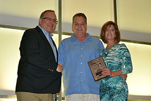
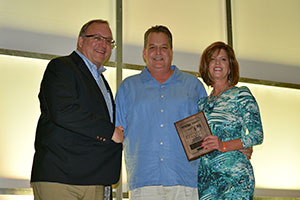
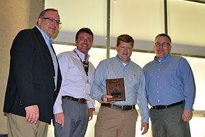
ESSE was a nominee and/or winner in almost all categories! Below is the detailed list of the awards ESSE received:
Eagle Award for Overall Top Dealer – ESSE was a nominee and finalist
Top Overall Sales Dealer – ESSE was a nominee and finalist
Top Overall Service Operations Dealer – ESSE was named as the overall top dealer of the year for Service Operations
Top Overall Parts Operations Dealer – ESSE was named as the overall top dealer of the year for Parts Sales and Operations
Top Overall GES Operations Dealer – ESSE was named as the overall top dealer of the year for GES (Telecom) Sales and Operations
Congratulations are in order for the entire ESSE team as all areas of the business were recognized and rewarded for an awesome performance! We thank all our employees for their hard work and dedication!
New 500kW Spark-Ignited Generator Set Expands Natural Gas Offering
The demand for larger, natural gas-powered products continues to grow both domestically and internationally. To meet this growing need, Generac unveiled its new 500kW natural gas gen-set, now the largest unit in the company’s broad spark-ignited industrial generator line.
Powering the new unit is a 25.8 L, 12-cylinder Generac engine that is turbocharged and aftercooled, producing a standby power rating of 500kW and prime power rating of 450kW. Previously, the largest nat-gas generator set Generac offered was standby rated at 400kW.
The new 500kW natural gas node was recently featured in the November issue of Diesel Progress, an issue that highlighted the latest advancements in power generation tools and systems. That article can be viewed in its entirety here.
Ideal for large standby power applications such as office buildings and mission critical data centers, the 500kW natural gas unit can be installed as a single engine generator set, or as part of Generac’s Modular Power Systems if generator paralleling is required for increased reliability, redundancy and flexibility, as well as greater scalability to accommodate future growth.
The new 500kW natural gas unit increases Generac’s effectiveness in meeting the growing demand for spark-ignited products in the U.S., and is also attractive to many of the global markets – where diesel fuel quality is low or the supply is limited – the company serves. For this reason, the demand for cleaner-burning industrial generators continues to grow worldwide.
Natural gas is a continuous, highly reliable fuel source even in the most common emergency situations. Additionally, it is recognized as a clean-burning fuel that easily meets EPA clean air standards, and – thanks to lower fuel costs and reduced maintenance – is often more cost-effective to operate than diesel-fueled alternatives.
Generac is recognized as the natural gas leader in the backup power industry, having been honored this past year by Frost & Sullivan with the prestigious Company of the Year Award. The company was cited for its contributions to the North American natural gas gen-set industry, including product innovations that have made gaseous-fueled generators more powerful and increasingly cost-effective, in addition to developing innovative solutions for industrial, commercial, residential and mobile applications that rely on natural gas. For a video that shares details about Generac’s accomplishments that led to the Frost & Sullivan award, click here.
Power Design Pro™: Motor Loads and Their Impact on Generator Sizing
This article highlights motor loads and the significant impact they potentially have on sizing the generator. Some starting loads tend to be higher and draw more power than running loads, so users have the option to adjust those settings and/or start motors in sequence to prevent specifying an oversized genset. Another benefit of Power Design Pro is that it intelligently accounts for potential issues with older motors and their starting sequences.
Motor Loading
To enter a motor load in Power Design Pro™, you simply select add “motor” from the left column. The motor load type supports motors of various starting methods including: across the line, reduced voltage, soft starters and variable frequency drives. It also supports adjusting the motor’s mechanical load level and the loads starting torque characteristics.
Power Design Pro allows the user to customize the motor’s running kW (rkW). In real applications, motors are loaded anywhere from 75% to 115%. The adjustable “motor load level” allows for fine tuning when measured running amp data is available or when detailed combination motor/load spec sheets clearly define the running amps.
In addition to fine tuning the steady state kW requirements, Power Design Pro also allows the dynamic characteristics to be adjusted. Low starting torque loads like pumps and applications with unloading valves or disconnect clutches tend to accelerate faster and impact the engine less than high torque loads like loaded conveyer belts. Power Design Pro allows for this dynamic starting difference by reducing the starting kW (skW) for the motor which potentially reduces the peak kW requirement for the genset.
Importance of Sequencing
Like all load types within Power Design Pro, motors can be placed into starting sequences that assume all the loads start concurrently (“steps”) or in a sequence that assumes non-concurrent starting (“groups”). Given that motors tend to cycle on/off based on a controlled process (pressure, temperature, human interaction, etc.), they rarely start concurrently. Within most applications natural sequencing tends to ensure this non-concurrent starting, though simple control interlocking or timer relays can prevent concurrent starting, if necessary.
Concurrent starting of motor loads within an application can result in a significantly upsized or oversized genset. When a motor starts, it draws a large inrush of low power factor current — lock rotor amps (LRA). Within Power Design Pro, this motor starting current is multiplied by voltage and expressed as starting kVA (skVA). When multiple motors start concurrently, each motor’s skVA become additive and the genset’s alternator must become large in order to limit the resulting voltage dip to an acceptable level. The larger the skVA for a load step, the larger the alternator and potentially the larger the genset.
Motor Starting Current
Power Design Pro uses the Association of Electrical Equipment and Medical Imaging Manufacturers (NEMA) and the International Electrotechnical Commission (IEC) data for starting codes, motor size and motor design. Power Design Pro allows the user to select a given motor’s skVA via the NEMA starting code (skVA/Hp) selection. The program defaults the motors starting code based on motor size and motor design (NEMA or IEC), but the user can always adjust this based on detailed motor data. Care should also be taken to get motor data for submersible well applications which typically have very high starting currents.
The motors starting requirements are also significantly impacted by starting method: across the line (full voltage), reduced voltage, soft starter, and variable frequency drive (VFD). Each of these starting methods has significant impacts on the motors skVA, skW, and harmonics.
Reduced Voltage Starting
If the starting method is reduced voltage, the available device types are wye-delta, various auto transformer configurations, and part winding. These settings will greatly reduce the required skVA and skW requirements.
The one issue with implementing these older methods of electrical/mechanical reduced voltage starting is the very significant possibility of the motor transitioning from reduced voltage to full voltage prior to the motor achieving full speed. An early transition to full voltage can cause near locked rotor current and may make the starting sequence seem like an across the line motor start.
The program will evaluate the available motor starting torque of the selected starting method against the loads selected mechanical characteristics. If the mechanical load characteristics (“motor load type”) are not compatible with allowing the motor to achieve full speed on reduced voltage starting, the program will assume an early transition and select appropriate skVA and skW values. This advanced feature of Power Design Pro attempts to avoid the early transition misapplication problem that is not typically accounted for by other manufacturers’ sizing programs.
Electronic Soft Starters
To overcome the limitations of electrical/mechanical reduced starting methods, the market has largely transitioned to electronic soft starters. If the motor starting method is soft starter, various current limit options are available. The current limit value is an adjustable parameter within most soft starters. The higher this setting, the higher the potential skVA load step (assuming a voltage stepped configuration) and the higher the momentary harmonic currents. Soft starter current limit settings typically vary with the load characteristics and desired motor acceleration time, but values in the 300% to 350% are common. The harmonic content will default to an appropriate value to match the current limit setting.
Two options are provided relative to how the soft starter builds output voltage: voltage stepped and voltage ramped. Most industrial soft starters support both modes. Voltage ramping gradually builds output voltage thus producing little to no skVA and skW load steps. This is the ideal configuration for a soft starter on a generator; however, this mode of operation may not be available on your particular soft starter. In the voltage stepped configuration, the soft starter steps voltage quickly up to the current limit point. This results in a skVA and skW load step in the system. This can be a significant disadvantage when coupled with a limited voltage dip tolerance. This is the case with the soft starter often utilized on hydraulic elevators.
Variable Frequency Drives
Creating the flexibility to operate a motor at various speeds, variable frequency drives (VFD) have become extremely popular in many applications. From a generator sizing standpoint, the generator powers the input rectifier stage of the VFD.
Power Design Pro has various rectifier and filtering options in support of the VFD motor option. The VFD’s rectifier configuration determines the device’s harmonic current spectrum and total harmonic content. The most common type of input for three-phase drives is six-pulse, non-filtered (default value). Though this is common in general equipment drives, many engineers in municipal pumping applications will incorporate harmonic mitigation in the system design. If harmonics have been mitigated, select one of the lower (less than 15% THID) options.
One of the major operational differences between VFD’s and soft starters is the impact that harmonics have on the system. VFD’s produce harmonics all the time where soft starts only produce them while starting the motor. Assuming natural or planned motor start-up sequencing, harmonics from soft starts are typically not an application issue. Given the high harmonic current content of unfiltered drives, it is essential that the generator sizing program perform harmonic analysis. Power Design Pro’s comprehensive harmonic analysis capabilities stand alone in the competitive market.
Advantages of Power Design Pro
Power Design Pro is a highly sophisticated generator sizing program that allows users to benefit from the advanced logic involved in the default selections, while also providing the flexibility to customize user inputs to precisely match the given real world situation.
The combined aspects of ease-of-use and powerful technological design makes Power Design Pro a trusted solution among consulting engineers and system designers.
Generator Breaker Requirements for Fire Pumps
The sizing and selection of the generator breaker(s) feeding the fire pump controller can be a muddled topic, so this article attempts to create greater visibility to NEC 695 requirements resulting in greater market alignment.
To start, however, let’s explore potential contributors to the confusion, including repeated requests for magnetic-only breakers or breakers sized for locked rotor current. Past versions (prior to 2014) of the National Electric Code (NEC) may have fed much of the confusion by interlacing the verbiage for the generator requirements amongst the normal serving utility. Misunderstanding may have also resulted from misinterpreting the following NEC 695 phrasing: “provide short-circuit protection only.”
Unfortunately, this historical confusion has resulted in the misperception that the generator should be designed with a “run to failure” mentality, meaning the generator should run to destruction while trying to carry fire pump locked rotor amps indefinitely. This mindset is potentially life threating considering the same generator carrying the fire pump will often power the building’s emergency system (exit lights, egress lighting, stairwell pressurization), which is the system designed to get people out of a burning building.
Although there may have been confusion, the 2014 version of the NEC does a much better job of identifying the generator requirements separate from the serving utility. Here’s an explanation of key code requirements:
NEC 695.3(D)(1): On-site Standby Generator… Capacity
“The generator shall have sufficient capacity to allow normal starting and running of the motor(s) driving the fire pump(s) while supplying all other simultaneously operated load(s).” On-site standby generators and the associated over current devices are only required to carry the normal starting and running currents. This is different from the utility source which is required to carry locked rotor current indefinitely.
NEC 695.4(B)(1)(c) Continuity of Power… Number of Disconnecting Means… On-Site Standby Generator
“Where an on-site standby generator is used to supply a fire pump, an additional disconnecting means and an associated overcurrent protective device(s) shall be permitted.” The generator is allowed to utilize an integral breaker. The generator is also allowed to feed a distribution panel which incorporates an additional breaker for the fire pump. This is different from the utility source which requires a tap ahead of the service and a single supervised disconnect sized for locked rotor amps indefinitely.
NEC 695.4(B)(1)(c) Continuity of Power… Disconnecting Means… Features… On-Site Standby Generator
“The disconnecting means for an on-site standby generator(s) used as the alternate power source shall be installed in accordance with 700.10(B)(5) for emergency circuits and shall be lockable in the closed position.” The separation of circuits’ concepts like “separate vertical sections” that are employed for emergency systems must also be employed for the fire pump breakers. NEC 695 doesn’t specifically state that the generator fed fire pump breakers are classed as an emergency system and as such can be located within an emergency system vertical section. This topic is open to some AHJ interpretation within the scope of NEC; however, IBC 403.4.9.1 defines a fire pump as an emergency load.
NEC 695.4(B)(2)(b) Continuity of Power… Overcurrent Devices… On-Site Standby Generators
“Overcurrent protective devices between an on-site standby generator and a fire pump controller shall be selected and sized to allow for instantaneous pickup of the full pump room load, but shall not be larger than the value selected to comply with 430.62 to provide short circuit protection only.” NEC 430.62 requires that the protective device be sized per 430.52 which limits the maximum inverse time breaker size to 250% of the motors nameplate rating. This sets the maximum size of the breaker. What about the minimum size of the breaker? What does “provide short circuit protection only” mean? NEC provides for short circuit, ground fault, and overload protection. Thus, short circuit only protection means no protection against ground fault or overload. NEC 430.32 defines overload protection at a maximum of 125% of the motor nameplate rating. Breakers sized larger than 125% provide no overload protection and thus provide short circuit only protection. The result of all this is that any breakers from the on-site generator source to the fire pump must be sized greater than 125% and less than 250% of the fire pump rating and support the temporary locked rotor amps associated with normal starting.
The code recognizes the standby generator has a disconnecting means (breaker) integrated into it. It also states that it is not required to tap ahead of this disconnect means which is a significantly different requirement then a utility service. So we continue to validate that the rules for the generator are quite different from that of the utility feed. What about the size the generator disconnecting means and overcurrent protection? The code clearly identifies the output requirements of the generator along with its internally integrated breaker that is sized for normal starting and running of the fire pump motor. Furthermore, the NEC handbook interpretation specifically states that the generators over-current protective devices are not required to be sized for locked-rotor current indefinitely.
Historically, NEC 695 has presented a significant interpretation challenge to system designers. The 2014 version has minimized much of the market confusion. After reviewing NEC 695, the use of magnetic only breakers, tapping ahead of the generator breaker, and breakers sized for carrying locked rotor amps indefinitely seem to be misinterpretations of previous code versions. The requirement to carry lock rotor amps indefinitely applies only to the utility source. As with all code interpretation issues, please consult with your authority having jurisdiction (AHJ) to ensure a common understanding on these issues prior to installation.
